Using when connected to a host
Connecting the Hub to a host computer
You can use either Thunderbolt™ host port on the rear of the hub to connect to your host system; there are two ports on the rear, so you can use one port to connect the host and the other port to daisy chain multiple hubs.
Connect the Product Name to your host system using a Host Connector Type cable. Using an incorrect host cable may result in the hub and all subsequent ports not being recognised by your host. You can use an optical cable to connect to your host as the Product Name is self powered. Thunderbolt™ 5 cables are backwards compatible, Also a Thunderbolt™ 2 cable with a Thunderbolt™ 2-3 adaptor can also be used with reduced data speeds
The Product Name must be connected physically to a host in order to communicate with the hub and devices. If you wish to connect to a hub remotely (not on the physical host it is connected to) it will still need to be connected to a host and have access to the Cambrionix Hub API which can then be connected to if the relevant steps have been taken, more information on remote access can be seen in the Cambrionix Hub API user manual, which can be viewed from the website. https://www.cambrionix.com/cambrionix-api
Connect the Product Name to your host
system using a
Host Connector Type cable. Using an
incorrect host cable may result in the hub and all subsequent ports not
being recognised by your host.
You can use an optical cable to connect to your host as the Product Name is self powered.
The Product Name must be connected physically to a host in order to communicate with the hub and devices. If you wish to connect to a hub remotely (not on the physical host it is connected to) it will still need to be connected to a host and have access to the Cambrionix Hub API which can then be connected to if the relevant steps have been taken, more information on remote access can be seen in the Cambrionix Hub API user manual, which can be viewed from the website. https://www.cambrionix.com/cambrionix-api
Authorising Thunderbolt™ hubs on Linux®
With Linux® systems, it is necessary to authorise/enrol the Product Name before it connects.
To do this, you will need to use "boltctl," which is used to control the Thunderbolt™ device manager. "boltctl" is the command-line interface to interact with boltd, the system daemon that manages Thunderbolt™ 3™ devices. Using "boltctl", input the following commands to authorise and enrol your Product Name.
Some useful information on this can be found at the following link.
https://manpages.ubuntu.com/manpages/focal/en/man1/boltctl.1.html
power [-t | --timeout seconds]
Power up the Thunderbolt™ controller. If the Thunderbolt™ controller is not in "native enumeration mode", it can be completely powered down by the host firmware/BIOS. On supported systems, there is an interface to "force" power the Thunderbolt™ controller. If supported, this command will request the daemon to do so. The daemon will keep track of all client requests and will release the force power override when the last request is released.
authorize DEVICE
Authorize a currently unauthorized device identified via its unique id (uuid) DEVICE. If a key is stored in the database, it will be used, given the security level of the domain supports secure device connection. Use boltctl list to find out the uuid of a device.
enrol [--policy default] DEVICE
Authorize and record the device with the unique id DEVICE in the database. If the domain supports a secure connection a new key will be generated and stored in the database alongside the device and vendor name. The key, if created, will be used in the future to authorize the device securely.
Charging
When the Host Port is connected to a local computer, the hub defaults to Sync mode and charge currents are determined according to USB Implementers Forum (USBIF) Super-Speed USB3 specifications. If the attached device complies with USB-IF Battery Charging specification BC1.2 and supports Charging Downstream Port (CDP), the hub can provide high-speed charging at Vbus Output Current, CDP Mode Max (A)A. If the connected device does not comply with BC1.2, the charge current will be limited to Standard Downstream Port (SDP) which isVbus Output Current, SDP Mode Max (A)A in compliance with USB specifications. Information on the different charging levels can be found in thePort Specifications section.
The Product Name also has an 'ALT Sync Charge' mode which is on by default, having this option selected will allow the Product Name to charge devices up to Vbus Output Current, ALT CDP Mode Max (A) A whilst syncing data.
If you wish to limit the charging to your devices whilst connected to your host system then you can disable CDP. You can disable CDP through Internal hub settings either by going through the advanced settings and turning "Sync charge" off or through the API and disabling it via code. For example, the instructions would be below using the command line.
The CLI commands for turning off the sync charge options, with a 1 or 0 per port.
settings_unlock
settings_reset
settings_set sync_chrg 0 0 0 0 0 0 0 0 0 0 0 0 0 0 0 0
settings_set alt_sync_chrg 0 0 0 0 0 0 0 0 0 0 0 0 0 0 0 0
reboot
This can also be done via the API if this is easier. Just supply that string (joined with \n) like:
cbrxapi.cbrx_connection_set(handle, "Settings", "settings_unlock\nsettings_reset\nsettings_set sync_chrg 0 0 0 0 0 0 0 0 0 0 0 0 0 0 0 0\nsettings_set alt_sync_chrg 0 0 0 0 0 0 0 0 0 0 0 0 0 0 0 0\nreboot")Note that settings_reset clears any previous settings, so if you need to retain something else, it would be better to issue settings_display first, which gives you the entire settings which you can then modify and re-issue in entirety.
For more information on this please see the internal hub settings section of CLI manual, which can be viewed from the following link. www.cambrionix.com/cambrionix-cli
Data Transfer
If you wish to transfer data, change applications, restore or update your mobile device, a data
connection to a local host computer is required. The Cambrionix Hub API and software is compatible with macOS®, Windows™ and Linux® operating systems and can transfer data between these operating systems and many mobile operating systems such as iOS™ and Android™.
In order to transfer data, connect the host port to your local (host) computer using a Host Connector Type compliant cable. Any devices connected to the hub will now appear as if they were connected to the host computer’s USB port.
To transfer data, connect the Thunderbolt™ port of your local (host) computer to one of the Thunderbolt™ ports on the back of the hub using a Thunderbolt™ 3 compliant cable (Thunderbolt™ 5 cable is backwards compatible). A Thunderbolt™ 2 cable with a Thunderbolt™ 2-3 adaptor can also be used with reduced data speeds. Any devices connected to the hub will now appear connected to the host computer’s USB port. The hub fully complies with SuperSpeed USB 3.2 and can provide up to 5Gbps data transfer speeds. A
Communication Interface and Protocol
The Product Name appears as a virtual COM port (VCP). On Microsoft Windows™, the system will appear as a COM port, the COM port number can be found in device manager. On macOS®, a device file is created in the / directory. S is an alpha-numeric serial string unique to each device
| /dev/tty.usbserial S |
Devices incorporate a USB to UART converter IC from FTDI International. On Windows 7 or later, a driver may automatically be installed (if Windows is configured to download drivers from the internet automatically). If this is not the case, or if a Mac® or Linux® platform is used, the driver may be downloaded from www.ftdichip.com. The VCP drivers are required. For Linux® or Mac computers, the default OS drivers should be used.
The default communications settings are as below, ANSI terminal emulation should be selected.
| Communication setting | Value |
|---|---|
| Number of bits per second (baud) | 115200 |
| Number of data bits | 8 |
| Parity | None |
| Number of stop bits | 1 |
| Flow control | None |
Connecting U8S for API
In order for the U8S to work correctly with the API there must be a USB Type-A to Mini-B cable that connects the control or update port to an expansion port on the same product. This is in addition to the USB cable that connects the host port to the machine running the API.
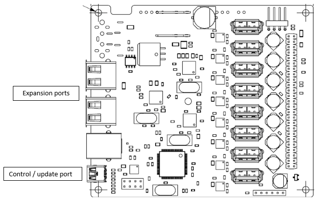
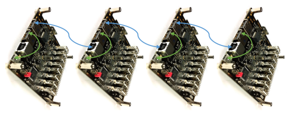
Figure 5.1
The green connections above are optional under normal circumstances when performing peer control, monitoring and data transfer (syncing) and are only required if you wish to up-date the firmware on all boards simultaneously.